
Logo by Paul
Hello all!
In this post, I will give you an introduction to the Roboost project – what it is, a summary of version one, and where the project is going – will be included. If you’re into robotics and are not afraid of a bit of maths, this post is for you!
What is Roboost?
Roboost, my robotics side project, is all about engineering a useful personal robotic companion. My fascination with robotics started in an informatics class in high school, where the teacher brought in a mini mobile robot (similar to this one) with which we had to implement basic functionality. This is where my passion for this topic ignited. I am still amazed by interacting with the world through code. The interface between environment and robot – sensors; and the interface between robot and environment – actuators and all the computation and brain behind it. From this class onwards, I left all the other topics behind and focused solely on robotics (which was also apparent in the worsening of my grades).
Long story short, when picking the topic for my final thesis, I did not have to think long about it. I wanted to create a mobile robot and implement the informatics part of it. So I convinced two of my classmates to create this robot with me. This is the start of the Roboost project and the birth of Version 1.
(Nearly) all the code can be found on my GitHub! If any questions arise, I’m more than happy to answer them in the comments.
Version 1
As already said above, we started this project as three classmates. One was in charge of the electronics, one of the mechanical design, and my task was to implement the brain of the system. The most important aspect of designing the mind behind a mobile robot is to make it aware of the environment and its position within it. With this information, the robot will be able to avoid obstacles and drive from point A to point B, which is the basis for more complex behavior.
To do this, there are several options available, some of which will be discussed in future posts. However, I decided to use a LiDAR sensor and the rotational information of the stepper motors to calculate the robot’s position.
What is a LiDAR sensor?
With a LiDAR (Light Detection And Ranging) sensor, the surroundings of a robot can be detected. This is usually realized with a ToF (Time of Flight) system – a laser beam that bounces off the obstacle and then gets measured by a light-sensitive sensor that calculates the time it took the light to travel to and from the obstacle. Using this information, the distance from the sensor to the obstacle can then be calculated through the speed of light. In the picture below, you can see the LiDAR sensor used in V1 of the Roboost project:
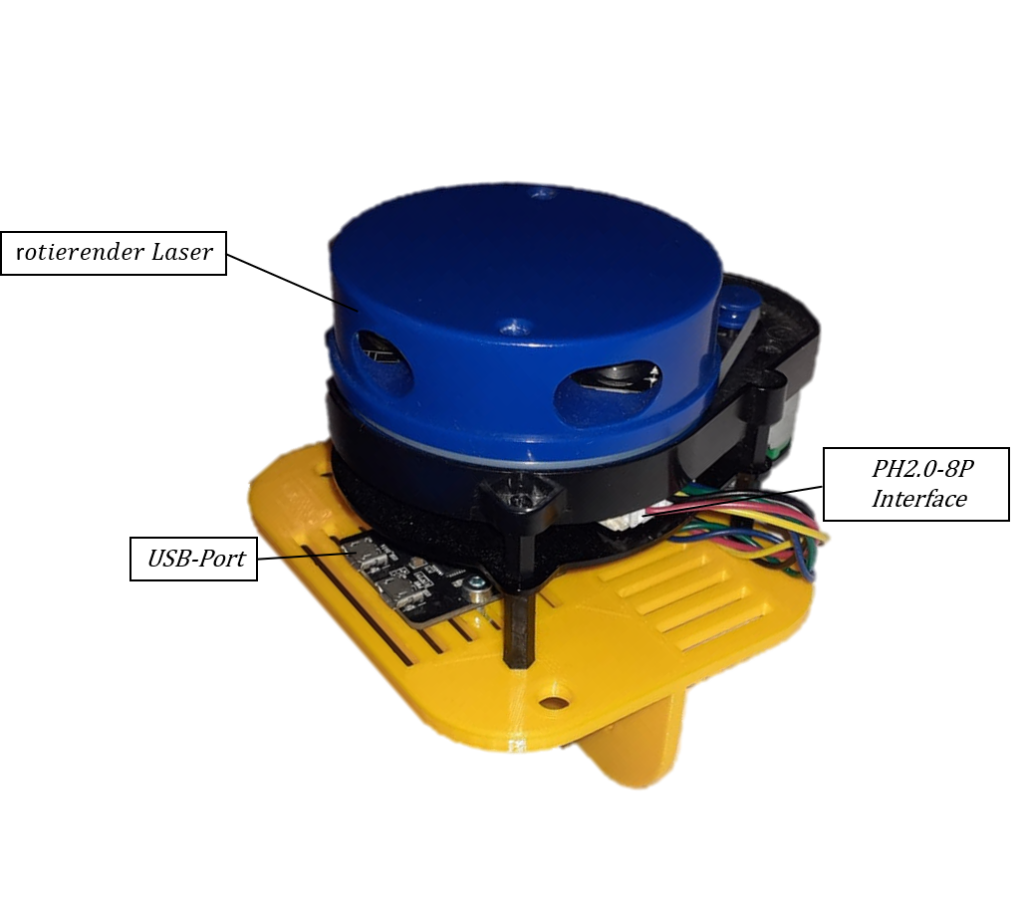
We designed a 3D-printed bracket to mount the LiDAR on the robot. I also had to implement a parser that converts the wired PH2.0-8P interface into usable sensor readings (in polar coordinates). A thing that complicated this whole issue was that the documentation of the sensor was in Chinese.
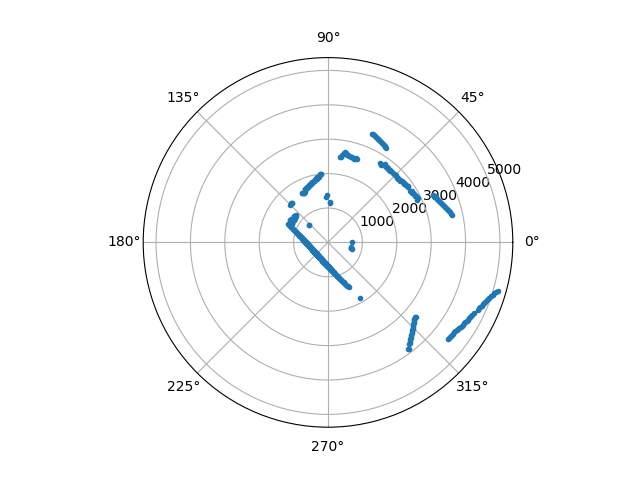
After finally receiving valid readings (15h later), I was able to visualize them using matplotlib in Python. In the image below, you can see a scan of my kitchen:
What is SLAM?
SLAM stands for simultaneous localization and mapping. It is a problem in robotics concerned with the creation of a map of an environment while simultaneously determining the robot’s location within that map. The goal of SLAM is to enable the robot to navigate autonomously in an unknown environment by building and updating a map of its surroundings. In the case of this project, I implemented an algorithm called EKF-SLAM (Extended Kalman Filter SLAM). This algorithm can be used to fuse two measurements of the same quantity together – the odometry (information about the rotation of the wheels) and LiDAR information about the position of the robot. In this article, you can see a sample implementation of a Kalman Filter. I will also make a separate post about the SLAM problem, as it is a really crucial, yet complex part of robotics. For now, it is enough to understand that the following steps are involved in EKF-SLAM:
- Initialize the robot’s position and the map of the environment.
- Use sensor measurements (such as the LiDAR data) to observe the environment and update the map.
- Use the robot’s motion information (such as odometry) to update the robot’s position on the map.
- Use the Kalman filter to estimate the uncertainty in the robot’s position and the map, and update them accordingly.
- Repeat steps 2-4 as the robot moves and gathers new sensor measurements.
- The final map obtained from the algorithm will contain the robot’s trajectory, landmarks, and obstacles in the environment.
In simple terms, the LiDAR is used to find landmarks in the environment. These landmarks can then be used to estimate the position of the robot. For further accuracy, this position estimation then gets combined with the odometry. After many hours of reading into the topic, I implemented it with C++ and Eigen (a library for linear algebra). Here is me testing the algorithm with the LiDAR attached to my head 🙂
Using RANSAC to extract Landmarks
RANSAC (RANdom Sample And Consensus) is an algorithm that can be used to detect walls in LiDAR data by identifying and extracting linear features that are present in the point cloud. The algorithm works by randomly selecting a subset of points from the point cloud, and using them to fit a line. This process is repeated many times, and the line that has the most inliers (points that are close to it) is considered to be the best fit and is therefore a likely candidate for a wall. Once a set of lines are obtained, they are clustered together to form a single wall.
The algorithm can then remove points that are consistent with the found planes, and repeat the process to find new planes. This is done until a stopping criterion is met, such as a certain number of iterations or a minimum number of inliers. The final result is a set of lines or planes that represent the walls in the environment.
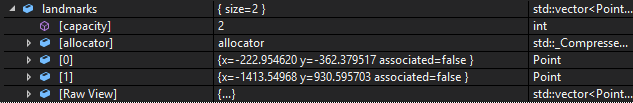
After tinkering for a while, I finally got the first two landmarks out of a sample data set:
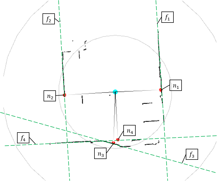
The picture below shows a screenshot of the visualization of the live LiDAR feed. I added the green lines that represent the walls extracted by the RANSAC algorithm, and the red dots are the landmarks used in the SLAM algorithm.
After implementing the RANSAC algorithm, I used the SFML library to create a simple GUI that displays important data and the live LiDAR feed. Below you can see a screenshot of the running system. Everything needed to be implemented in several threads to run smoothly (also using semaphores to prevent race conditions).
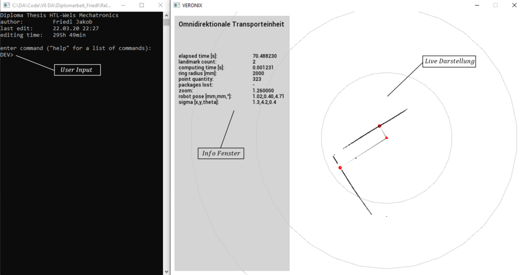
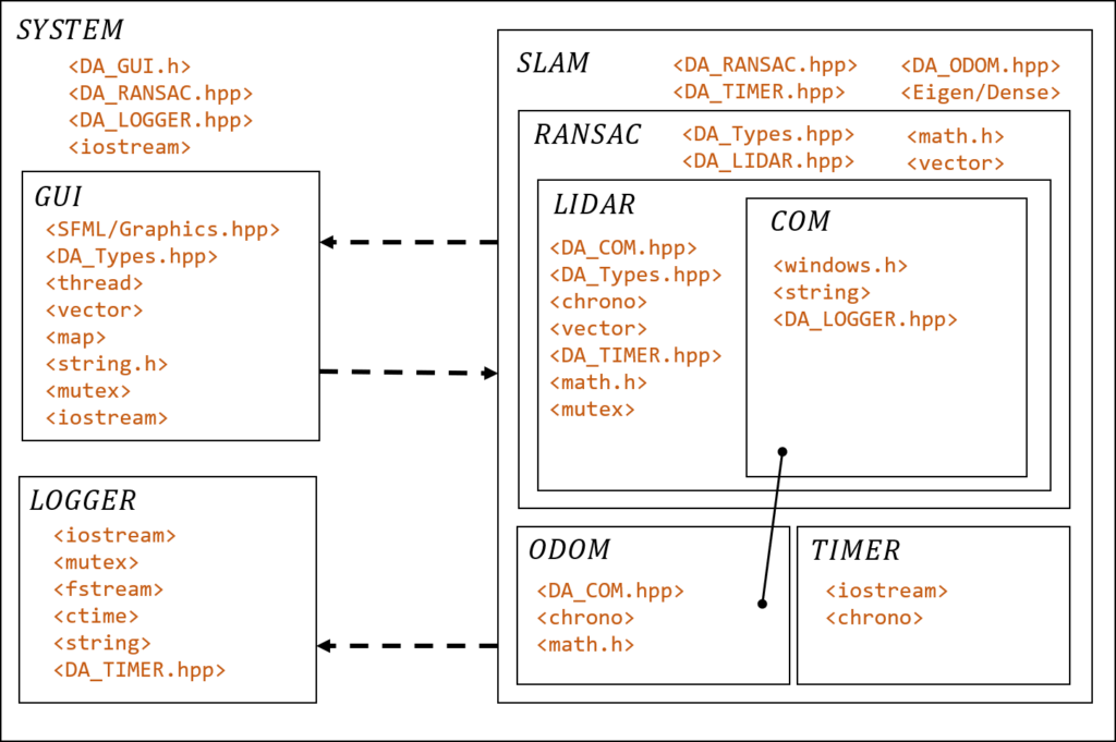
In the next picture, you can see the system architecture, as well as all the dependencies. Note again, that all the code can be found on GitHub.
After about 300h of coding and implementation hell, here is a short video of our abomination in action:
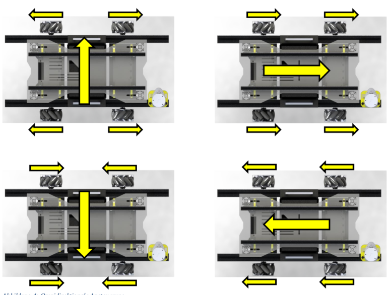
Sadly, toward the end of the project, a certain pandemic started (I don’t know if you’ve heard about it). In any case, we were not able to finish the project completely due to all the lockdowns. For example, the wheels you see on the robot are so-called mecanum wheels that would allow the robot to move in any direction (omnidirectional); we were not able to implement this.
Here is a quick summary of the principle of mecanum wheels:
As everyone took their own ways after high school, and the project had been sponsored by the school, we had to leave the robot there. However, I was not satisfied with the outcome, so I started to work on version 2 (the post will come up soon).
Takeaways
- I overcomplicated the implementation as ROS could have been used
- We used too weak motors
- The led batteries were too heavy
- Robotics is fun xD
Let me know your thoughts and questions in the comments! Stay tuned for a post all about version 2 (or take a look at it on my blog). Thanks for sticking around! 🙂
[…] Roboost V1 […]
Which platform was used to write the software for the project?Thanks for information <a href=”https://bif.telkomuniversity.ac.id/skala-likert-definisi-fungsi-dan-panduan-lengkap/”>Kehidupan Kampus</a>