Version 2 of my Roboost project! As you’ve seen in the previous post, the former version had quite a few problems, although it wasn’t finished completely. So after finishing school, I decided to tackle the issue again. This time, I did not only want to do the programming, but I also wanted to learn more about electronics and manufacturing. The picture above shows the previous version on the left, and version two on the right. As V1 belonged to my school, I had to get every component anew. One good thing about that was that I was able to choose the parts to use more carefully, resulting in a lighter, more compact design.
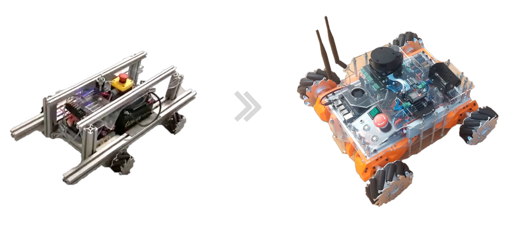
For example, the lead-acid batteries from V1 have been replaced with a 8Ah 12V LiPo, which is way lighter. Also, as the software of the previous version ran on Arduino Nanos and a laptop, I chose to do the hardware control (PID, sensor reading, etc.) on two ESP32 with custom motherboards. For the main processing, I used a Jetson Nano running ROS on Ubuntu, which simplified the software a lot.
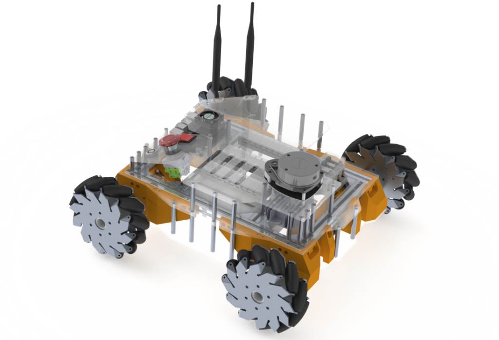
For the mechanical construction, I wanted to visualize the design in Solidworks first. Below you can see a rendering of the design.
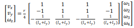
To make use of the capabilities of the mecanum wheels, the following formula describes the connection between the angular velocity of the four wheels (on the right side of the equation) with the resulting velocity of the robot (on the left side of the equation; vx -> velocity in the x direction, xy -> velocity in the y direction, wz -> angular velocity around the z axis).
This then had to be implemented in code to run on the ESP32 that controls the motors. The information flow is as follows:
- The goal waypoint is described by the user in the Gazebo ROS interface. This can be accessed by connection to the Jetson Nano via a remote desktop.
- ROS calculates the path to follow in the surrounding environment (perceived by the LiDAR) to get to the goal.
- While doing SLAM, the wanted velocity of the robot gets sent via ROSSerial to the ESP32.
- The ESP32 uses the formula above to calculate the wanted angular velocity of each of the four wheels
- With a PID controller, each wheel is trying to reach that wanted velocity.
- The actual velocity of the robot is calculated again using the formula above and sent back to the Jetson Nano to use as correction for the ongoing SLAM algorithm in ROS
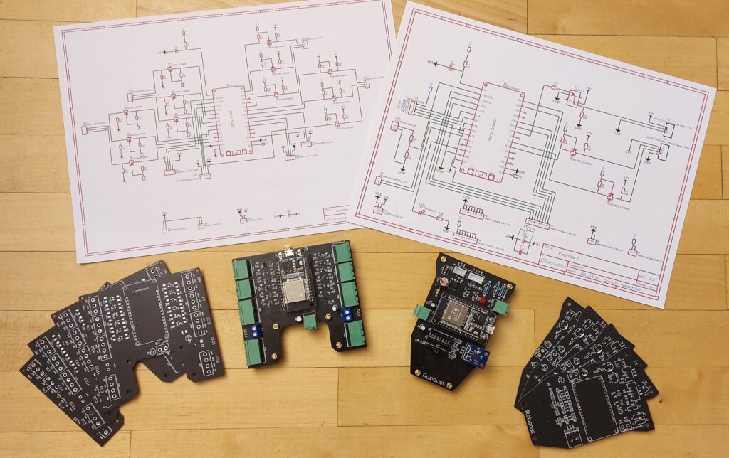
The Picture below shows the custom PCBs (Motorshield on the right, Sensorshield on the left). These are designed with EasyEDA and manufactured with JLCPCB. The minimum order amount was five PCBs per design, therefor the unpopulated ones.
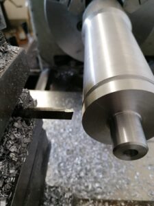
To connect the mecanum wheels to the motor shaft, aluminum connectors were made on the turning machine. As I’m not that experienced in using this machine, the holes did not come out with the quality needed, which will come as a problem later on. The result was, that when turning all the wheels, one of them might not touch the ground and slips, which results in unpredictable movement.
At last, here you can see the finished version 2 of the Roboost project, demonstrating the side-to-side movement using the mecanum wheels.
Although the robot itself might look promising, there are still many problems with the design. For example, as stated above, if one wheel slips, the movement of the robot gets out of track. This could be prevented by using suspension on all the wheels. However, for V3 I decided to ditch the mecanum wheels altogether to use a different drive system, called swerve drive. This should allow the robot to move in outdoor environments and be a more reliable solution.
For more information on the Roboost V2 robot, take a look at the dedicated post on my website. If you have any questions, please leave a comment!
Thanks for sticking around! 🙂
[…] Roboost V2 […]
Where were the main parts for the project purchased? Thanks for information <a href=”https://bif.telkomuniversity.ac.id/skala-likert-definisi-fungsi-dan-panduan-lengkap/”>Kehidupan Kampus</a>
All over the place. Mecanum wheels, motors and battery+bms on aliexpress. Jetson Nano and many other parts on Amazon. The metal and plastic hardware parts in a local hardware stors 🙂